 Scopique
I had a lot of projects done in After Effects, and I mourn the loss of access to AE more than any other Adobe product, but that’s not the point of this post. Instead, since I have been spending all of my time watching videos on how to use Davinci Resolve Fusion, I thought it was time to see if I could recreate AE projects using Fusion.
The first historical project I thought I would tackle is (what I assumed would be) one of the easiest and most obvious: planar tracking. This is one method of inserting footage (we’ll call it “B”) into footage (we’ll call it “A”) and having the B-footage “track” with any motion that we might experience in the A-footage. Since this is such a common need, both After Effects and Resolve Fusion can do it, and there’s a application called Mocha that does nothing but track footage for other applications to use.
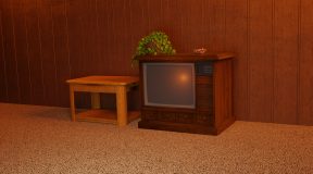
Back in 2019, I recorded some footage of a TV I had mounted on my wall and on this screen I was displaying a chroma-key image with some “trackers” on it.
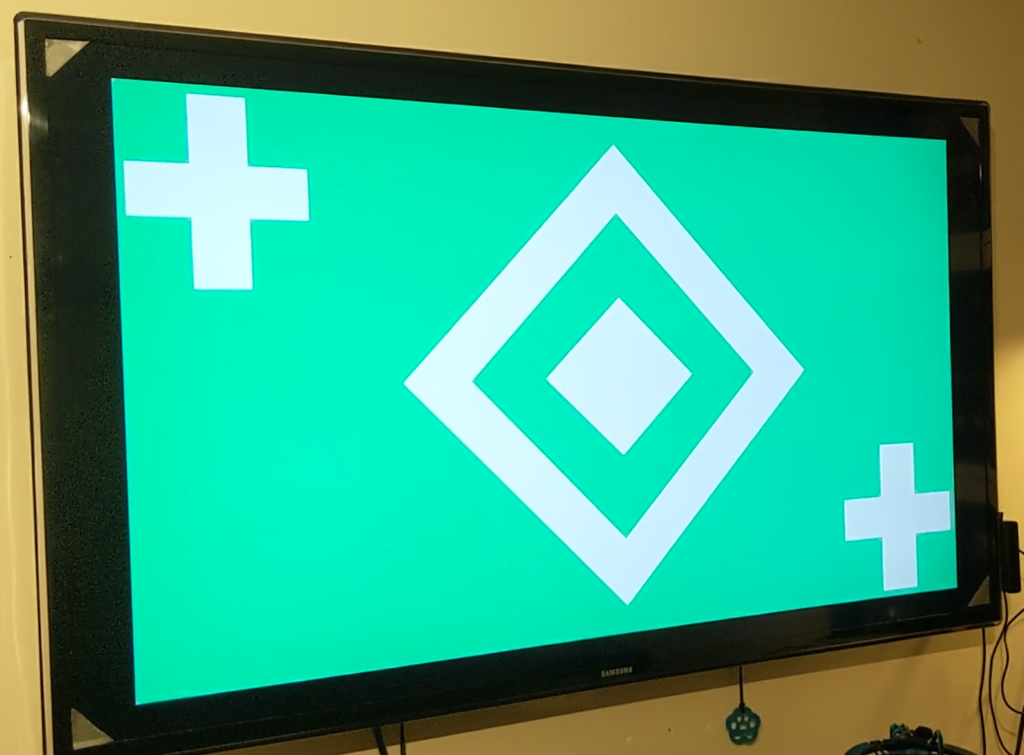
I can’t remember exactly how I managed to pull it off, but I replaced that test pattern with a video taken from Guild Wars 2.
For my first Fusion project, I went back to my original source files (thank gawd I was paranoid about losing the source files and kept them) and loaded the TV video into a new Fusion composition.
About Nodes
Unlike AE which uses the non-linear editor (NLE) format effectively layering effects on top of one another, Fusion uses the concept of nodes. The first node will always need to be some form of media input, usually from the editor timeline, and the last node will always be a media output. The effects applied to the media occur between the in and out points and is done by nodes; each node has a specific job: the footage enters a node, the job is executed, and the results exit the node. By linking nodes, we can create order-specific effects that build upon work done by previous nodes until our transformed footage is returned to the editor.
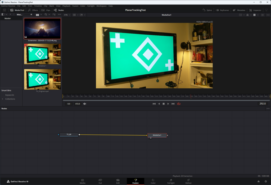
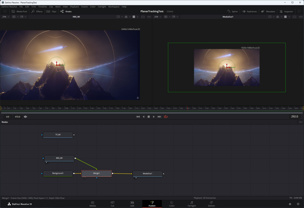
Here’s the start of the planar tracking test in Fusion. I’ve got the original footage as the “TV_MI” node (TV MediaIn) which only connects to the “MediaOut1” node. Viewing this in the monitor at the top of the screen shows just the footage as it was imported: nothing was done to it.
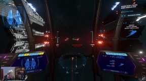
The first order of business is to get a plain old image in there — I’m not using another video like I did in the original, for simplicity’s sake. I chose a screenshot I took from 2023’s CitizenCon presentation which I thought looked cool.
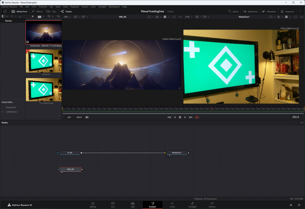
The idea is to put the image inside the TV and to have it “track” as the camera jiggles and shakes (I could stabilize the footage, but where’s the fun in that?). Right out of the gate, there is a problem, and it’s a big one: The original footage was taken on my DJI OSMO at 1920×1080, but the screenshot I want to insert was taken at 3440×1440. Normally the solution would be to resize the image, but then we’re talking about possible loss of fidelity and besides, if I were using video footage and ran into the same issue, I would be hard-pressed to resize and resample an entire video.
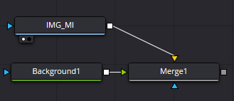
The solution was to force the image to resample to the project dimensions of 1920×1080. I did this by dropping the image into the node canvas (named “IMG_MI”) and the merging it with a background node. A merge node brings two elements together and outputs them as one. A background node is like a “shape layer” in AE: it’s basically just a blank canvas that we can color or use as a base for other nodes which Fusion can’t work with in a native form.
But there was another problem. Nodes can have several input ports, but generally only one output port. The type of input port is determined by the function of the node; some nodes have only one input while some have unlimited (or so they say). A merge node has three inputs: a foreground, a background, and a mask. By just dragging the output ports of the “Background1” and “IMG_MI” nodes into the “Merge1” node, the “Background1” is set as the foreground, and the “IMG_MI” is set as the background. This is the result:
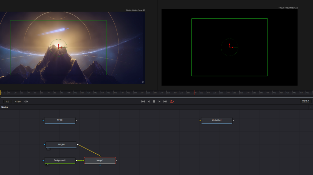
The green rectangle is the resolution we want: 1920×1080. As we see on the left, the image exceeds that rectangle. As we see on the right, the image is just too damn big: it blows out the dimensions of the video, and will certainly not fit inside the TV. To fix this, I had to select the “Merge1” node and press CTRL+T which swaps the foreground and background input sources, resulting in this:
The image on the right still exceeds the bounds of the 1920×1080 resolution (as shown by the green frame), but anything outside of those dimensions is masked out which is what we want. If we didn’t do any of this, the 3440×1440 image would force a size change of the project, leaving the little 1920×1080 video floating in a much larger space and that is a massive problem. I tried using a transform node on the image, but that didn’t work as expected, but thanks to the help of a reddit post, I found this background-merge solution.
Chroma Replacement
The next step was to do a chroma replacement of the green-screen. I connected the “TV_MI” input to the “MediaOut1” node, and dropped a Delta Keyer node in between. This node uses an eyedropper tool which can sample a color in the footage that we want to key out, and the result is pretty damn amazing with just one click. I don’t remember having that kind of instant success in AE, but it’s been quite a few years now.
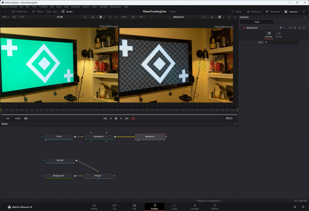
This “removes” the sampled color wherever it’s found in the footage, leaving only an alpha channel behind.
Inserting the Image
This was unfortunately very tricky because in order to understand Fusion’s nodes, I had to understand order of operations and the proper use of merge nodes and I got turned around a few times trying to figure it out.
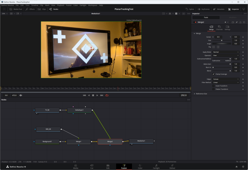
So far I have completed two operations in the project. The first was to get the 3440×1440 image to fit within the 1920×1080 canvas size without forcibly resizing it. The second was the chroma replacement. The image resize combined a background node with the image node using a merge node. I thought I could simply connect the “DeltaKeyer1” node to the merge node as a mask and then output the merge node to get the image inside the tracked TV; maybe then I’d have to invert the mask and the result would be what I was looking for. Sadly, that was not the case.
What I did need to do was to merge the existing merge node with another merge node that connected to the output of the “DeltaKeyer1” node, and use the output of that merge node as the input to the “MediaOutput1” node. In retrospect this makes sense: I needed the TV footage to be the foreground, and the result of the image resize merge to be the background; the TV was never going to be the mask of the image as a regular overlay, but instead needed to be merged with the output of the image to get the image in correct location.
But wait! If I were to show you the video, you’d see the image inserted into the TV (with the white tracking marks present, but that’s another task someday), but it would remain static as the footage bobs and weaves. As cool as it is to display the image in the TV, that’s not what I’m after here.
Planar Tracking the TV
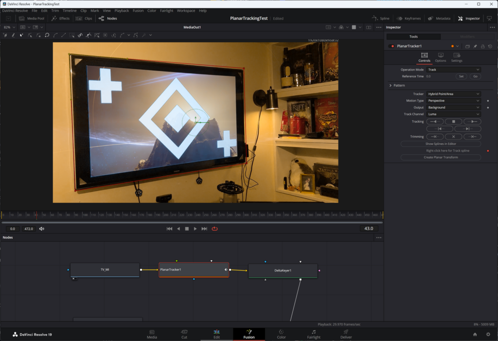
I inserted a Planar Tracker node in between the “TV_MI” and “DeltaKeyer1” nodes. As the name implies, this node requires the definition of some “plane” in the footage that we want Fusion to “track”. Tracking will record changes in the position of these points and/or the plane they create over the course of the footage, inserting keyframes in every frame where the tracker detects movement. In the screenshot above, I outlined the entire TV because the tracker needs to know some plane, not necessarily the area I want to work with — i.e. the screen portion where I’m doing replacement. I then had Fusion follow that rectangle over the course of the footage. The result is a new node called Planar Transform. This contains the data about the motion recorded across the lifetime of the footage. Once this data has been collected and verified, I deleted the planar tracker node as it’s only use was to create the data.
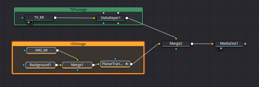
To use this data, I dropped the “PlanarTransform1” node after the first merge node in the image comp. As the image is processed through the node tree, the planar tracking data node will apply the motion data from the recorded plane to the image, making the image output move in time with the swaying of the camera.
Here’s the final node tree, organized for clarity (I hope).
And here’s the final video!
I didn’t deal with the tracking marks that were part of the video on the TV because I wanted to write this post; I am not a Fusion expert, and I got the details from from a video from motionVFX. As always, I write these posts on one hand to talk about them with people, and on the other hand to serve as a reminder for my future self about how I managed to achieve some task.